In this article we look at a dot matrix display from keyestudio which is controlled by a HT16K33
The 8X8 dot matrix is composed of 64 light-emitting diodes, and each light-emitting diode is placed at the intersection of the row line and thecolumn line. When the corresponding row is set to 1 level, and a certain column is set to 0 level, the corresponding diode will light up
The module uses the 28-pin HT16K33 LED controller / driver chip from Holtek.
The HT16K33 is designed as a multi-functional device for driving a number of LED display applications including dot matrix, 7-segment and alphanumber 14-segment displays. It also includes a keyboard scanner by multiplexing the same pins for both driving the display and looking for key presses.
It can address up to 16 rows with 8 common pins, so can support up to 128 LEDs in a matrix or eight 7-segment or alphanumeric displays.
The module has an easy to use I2C interface.
The default I2C address is 0x70. Address lines A0-A2 allow the address to be set to the range of 0x70 – 0x77 by solder bridging the pads to pull that pin high. Bridging all 3 pads results in the address 0x77. My module was set 0x70.
The I2C lines have 10K pull-up resistors included on the module.
Parts Required
You can connect to the module using dupont style jumper wire.
| Name | Link |
| Arduino Uno | Aliexpress link |
| HT16K33 matrix |
|
| Connecting cables | Aliexpress product link |
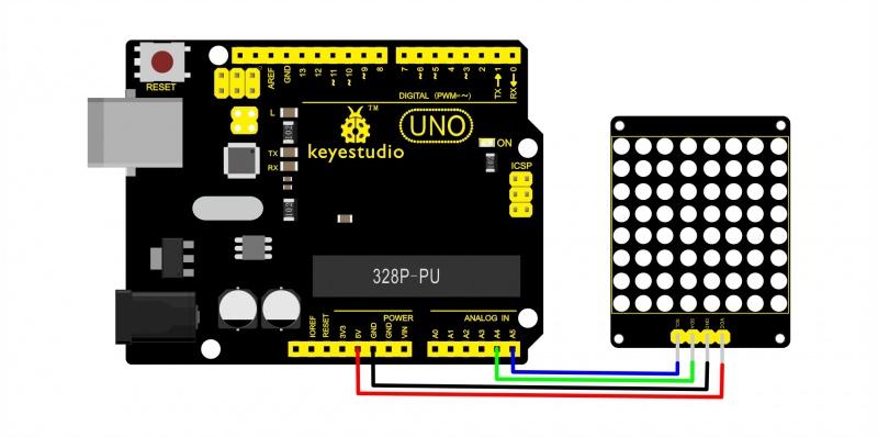
Schematic/Connection
Module Arduino
SCL —– A5
SDA —– A4
Gnd —– Ground
Vcc —– 5v
It should be noted that my matrix cannot have the I2C address selectable and features small surface mount leds, this was part of a Raspberry Pi Pico kit
Code Example
This example uses the library from the following location – https://github.com/lpaseen/ht16k33
The test example is below which shows some of the functionality well
[codesyntax lang=”cpp”]
#include "ht16k33.h"

// Define the class
HT16K33 HT;

/****************************************************************/
void setup() {
    Serial.begin(115200);
    Serial.println(F("ht16k33 light test v0.01"));
    Serial.println();
    // initialize everything, 0x00 is the i2c address for the first one (0x70 is added in the class).
    HT.begin(0x00);
}

/****************************************************************/
void loop() {
    uint8_t led;

    Serial.println(F("Turn on all LEDs"));
    // first light up all LEDs
    for (led=0; led<128; led++) {
        HT.setLedNow(led);
        delay(10);
    } // for led

    Serial.println(F("Clear all LEDs"));
    //Next clear them
    for (led=0; led<128; led++) {
        HT.clearLedNow(led);
        delay(10);
    } // for led

    //Now do one by one, slowly, and print out which one
    for (led=0; led<128; led++) {
        HT.setLedNow(led);
        Serial.print(F("Led no "));
        Serial.print(led,DEC);
        Serial.print(F(": On"));
        delay(1000);
        HT.clearLedNow(led);
        Serial.println(F(" Off"));
    } // for led
}
[/codesyntax]
You should various leds lighting on the matrix, there are other solutions I looked at from Adafruit and Seeedstudio but this seemed to be the easiest.
