In this article we look at another board which looks like it would be a good fit for beginners.
Now the normal combination is to buy a shield which has some external components on it and fit in on your Arduino – in this case we have a combination, an Arduino Uno with the components already present.
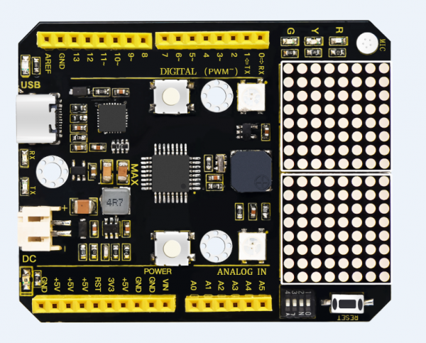
The Keyestudio Max development board is an Arduino uno-compatible board, which is based on the ATmega328P MCU. The MAX development board integrates many onboard resources and it is still compatible with all arduino shield boards.
Here is an image of the board in question – you can see that the Arduino headers are at the front of this board but that you can still install a shield, one thing I saw was that the buttons have plastic caps which raises them higher than the headers, you may have to remove these – a couple of the shields I tried had long pins anyway so they are not flush with the headers but I know some have shorter pins.
The LED matrix is also higher than the header – so if the shield has an over hang at the A5/D0 side again you may have to watch out.
Features
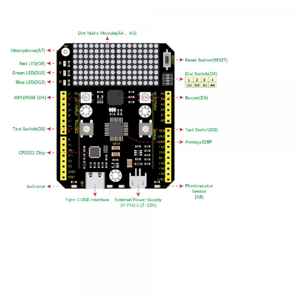
The following LEDs are fitted to the board
red LED which is connected to D8
green LED which is connected to D10
yellow LED which is connected to D13
There are 2 6812 RGB LED which are connected in series that uses D4
There are two switches which are connected to D2, D3
There is a buzzer which is connected to D9
There is a microphone sensor which is connected to A7
There is a light sensor which is connected to A6
There is a 8*16 dot matrix LEDs driven by an HT16K33 I2C driver chip that uses A4,A5 (I2C interface)
4-digit DIP switch which uses D2, D3, A4, A5. Which can enable or disable the buttons and display mentioned earlier
Here are the features
Development
I plugged this board in to my PC, fired up the Arduino IDE and the board was recognized as an Arduino Uno
Code Example
This simple example cycles through the 3 LEDs
int redled =8;
int greenled =10;
int yellowled =13;

void setup()
{
pinMode(redled, OUTPUT);
pinMode(yellowled, OUTPUT);
pinMode(greenled, OUTPUT);
}

void loop()
{
digitalWrite(greenled, HIGH);//// turn on green LED
delay(1000);
digitalWrite(greenled, LOW); // turn off green LED
delay(1000);
digitalWrite(yellowled, HIGH);// turn on yellow LED
delay(1000);
digitalWrite(yellowled, LOW);// turn off yellow LED
delay(1000);
digitalWrite(redled, HIGH);// turn on red LED
delay(1000);
digitalWrite(redled, LOW);// turn off red LED
delay(1000);
}
Neo Pixels example
#include <Adafruit_NeoPixel.h>
#ifdef __AVR__
#include <avr/power.h>
#endif

#define PIN 4

// Parameter 1 = number of pixels in strip
// Parameter 2 = Arduino pin number (most are valid)
// Parameter 3 = pixel type flags, add together as needed:
//   NEO_KHZ800  800 KHz bitstream (most NeoPixel products w/WS2812 LEDs)
//   NEO_KHZ400  400 KHz (classic 'v1' (not v2) FLORA pixels, WS2811 drivers)
//   NEO_GRB     Pixels are wired for GRB bitstream (most NeoPixel products)
//   NEO_RGB     Pixels are wired for RGB bitstream (v1 FLORA pixels, not v2)
Adafruit_NeoPixel strip = Adafruit_NeoPixel(2, PIN, NEO_GRB + NEO_KHZ800);

// IMPORTANT: To reduce NeoPixel burnout risk, add 1000 uF capacitor across
// pixel power leads, add 300 - 500 Ohm resistor on first pixel's data input
// and minimize distance between Arduino and first pixel.  Avoid connecting
// on a live circuit...if you must, connect GND first.

void setup()
{
  strip.begin();
  strip.show(); // Initialize all pixels to 'off'
}

void loop()
{
  // Some example procedures showing how to display to the pixels:
  color(strip.Color(255, 0, 0), 50); // Red
  color(strip.Color(0, 255, 0), 50); // Green
  color(strip.Color(0, 0, 255), 50); // Blue
}

// Fill the dots one after the other with a color
void color(uint32_t c, uint8_t wait)
{
  for(uint16_t i=0; i<strip.numPixels(); i++)
  {
    strip.setPixelColor(i, c);
    strip.show();
    delay(wait);
  }
}
LDR example
int ldrVal = 0;   //set analog pin 0 to read the voltage value of photosensitive diode

void setup()
{
  Serial.begin(9600);  // set serial baud rate to 9600
}

void loop()
{
  ldrVal = analogRead(A6);
  Serial.println(ldrVal);
  delay(1000);
}
So there you go, you can easily combine the features of the board – so for example Traffic lights with the LEDs, LDR switches on the neopixels when its dark, sound activated light and others
Cost
This cost me under £22 from Aliexpress, I actually got it on offer so it actually came in at around £17. So for me that is a pretty good deal for a well made board with plenty of features.
If you are starting out you can start your Arduino development for about £22. Pretty decent.
| You can get one here -> | Aliexpress link |
